Foreword Techtipps:
We would like to take care of some basic topics, which hopefully will help the beginner in our beautiful hobby.
The old hands, who know exactly how to implement a project, should be told here that there is usually not only one right way.
In this section Fumotec does not want to question anybody's conversion or any procedure, we would like to give you some useful tips and tricks. Of course, it is up to each individual to decide for himself whether it makes sense to do so and if so, to implement it. Our aim is to offer interested model builders added value and to offer our customers solutions which also address frequently asked questions.
But it should not be a classic FAQ page. We try to offer a little more in a certain regularity.
Have fun with our FTT - the Fumotec Tech Tips!
With the introduction of lithium polymer rechargeable batteries, short lipos and brushless drives, we were able to create unexpected performance possibilities in our beautiful hobby.
But the new technologies did not only bring advantages. The initially more complicated handling still discourages many model builders. That makes it all the more important to know your tools of the trade. That's why we decided to give you useful and helpful explanations about model building and especially about our Fumotec models under the heading Tech Tips.
Performance data and notes on the battery - an example:
Battery 3S1P with 5000mAh and 35C discharge current and max. 3C charge current.
3S1P means that the battery is made of 3 cells soldered in series (positive pole to negative pole) (S stands for that). The P stands for parallel and means that, in addition to serial soldering, the battery also has parallel soldering (positive pole to positive pole, negative pole to negative pole) in order to increase capacity and load capacity (discharge and charging current). In general one uses almost exclusively serially soldered battery packs, so here is 1P.
5000mAh means that the capacity of the battery is 5000 milliampere hours or 5 ampere hours. This number describes the amount of power the battery has. In the same model you can operate longer with a 5000mAh battery than with a 4000mAh battery.
11. 1 V means that the battery has a rated voltage of 11. 1 V. Each lithium polymer cell has a rated voltage of 3. 7 V. This voltage is multiplied by 3 because we have 3 cells in the battery. In this way we obtain the nominal voltage of 11. 1 V. The cell has the nominal voltage approximately in the delivery condition, here it is only approx. 20 % fully charged. The practical operation should already be finished when the nominal voltage is reached. A fully charged lithium polymer cell has a voltage of 4. 2 V. Multiplied by 3, this results in a total voltage of 12. 6 V in the fully charged battery. This is also the switch-off voltage for the charger.
35C means that the battery may be permanently loaded with a maximum of 35C (35 x 5Ah results in 175 Amps).
3C means that the battery may be charged with a maximum charge current of 3C (3 x 5Ah is 15 Amps). Lower currents protect the battery.
Brushless controllers are now also part of a model's basic equipment in functional model construction. Be it as a pump drive or as a traction drive as in our models.
But where "brushed"; systems usually work "plug and play";, "brushless"; systems need a little more attention beforehand. But in return you will be rewarded with a longer battery life, more performance and less wear and tear.
TIMINGWERT UND POLZAHL
Timing is nothing more than a time setting proportional to the position of the rotor in degrees.
The timing of electric motors is similar to the function of early ignition in combustion engines.
The correct timing setting is very important to optimize an engine.
Responsible for the timing setting is the controller that passes the voltage distribution to the motor.
If a controller switches voltage to a motor, the voltage is immediately applied at full level,
However, the current does not flow immediately in full strength, but only occurs with a time delay.
This of course costs motor power, because the magnetic fields in the coils are built up or dismantled too late.
The magnetic fields do not fit optimally to the magnets without a setting.
A sign for wrong timing are the "screeching/squeaking noises"; of the engine.
These are not only disturbing but can also damage the engine.
So the tension must arrive earlier.
Of course, all this happens within fractions of a second and varies from engine to engine.
The timing depends on the pole number, inductance and the operating voltage.
Fewer poles usually have lower timing values.
Simplified means :
Low timing values = lower current = less power = lower engine speed = less heat in the engine = longer battery life.
higher timing values = higher current = more power = higher engine speed = more heat in the engine = shorter battery life.
Guide values for timing selection (observe manufacturer's instructions):
0°- 12° for 2 - 6 pole motors (internal rotor).
13°-- 22° for 6 - 12 pole motors (external rotor).
22° - 30° for 12 - 16 pole motors (large external rotor).
Summarized again :
The meaning and purpose of timing is the time adjustment of the commutation time with respect to the magnetic field. This is necessary because the motor winding is charged with inductance, which means that the current does not start until later, means with a delay. Therefore, the current flow must be used earlier. The exact timing value must be matched to the engine.
The higher the timing, the more current the motor draws. The appropriate setting must be selected depending on the number of poles of the brushless motor.
Without a screw locking device, a permanent operation without failures is not possible with functional models (by the way, with almost all other models as well).
All drive elements must therefore be secured. In addition to the generally different strengths of the screw locks offered on the market, however, it makes a considerable difference how the screw lock is used.
Screw locking in the thread or on the screw? For normal screw connections where a secure connection is important, but both the screw and the part to be mounted on a shaft (gearwheel, hub, or whatever) want to open and dismantle again without problems, it is recommended to apply the screw lock to the thread of the screw. When screwing in, a part of the screw locking device wipes off to the outside and can be wiped off. Thus the screw is secured in the thread, but can be loosened again. The part mounted on a shaft can be easily removed.
Wenn´s really depends on it. . . . . .
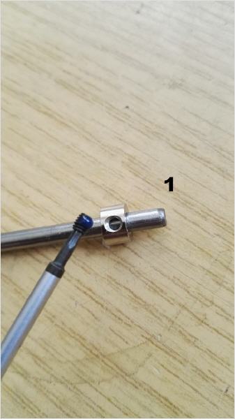
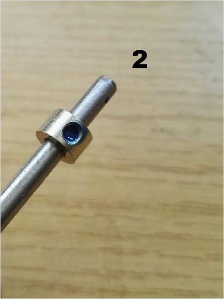
When it comes to drive components, especially where high torques have to be transmitted (here especially chain drives and slewing gears in excavators), or other places where you want to be on the safe side, you should go another way. It is better to apply the screw lock to the thread here. When the screw is screwed in, the excess screw lock is pushed forward. The screw acts now like a piston in the cylinder, and pushes the screw lock in front of itself until the screw lock is then pressed between gear and shaft (or whatever is mounted straight). Since screw locking is a kind of metal glue, the screw itself is of course secured, but the gear wheel is also glued to the shaft. A connection that even with medium strength screw locking can usually only be loosened by strong heating.
1. the suction line (Fumotec Shop ID:15-13) between the pump and the tank
should always be as short and thick as possible.
2. if possible, no elbow fittings with low passage
to use.
If elbow fittings are required, then with 90° bend for
full cross-section.
Use e. g. plug connection 90° with 6mm (Fumotec Shop-ID. ):
15-59) and 8mm (Fumotec Shop-ID:15-58) or our M5 Brass
Contra-angle handpieces (Fumotec Shop-ID:15-136)
3. the oil level in the tank should always be above the pump, but at least at the level of
the same height so that the pump does not have to suck in the oil.
4. the piping between the pump and the valve block should be thicker than the
individual lines from the valve block to the cylinders. (e. g. Ø6mm
Fumotec Shop ID:15-12)
5. the return lines (Fumotec Shop-ID:15-14) from the valve block to the
tank should ideally be thicker than the one from the pump to the
Valve block to avoid backpressure. (Double return if necessary)
Execute)
6. the return lines in the tank should always be located below the oil level
otherwise the oil will foam up.
7. the return and suction lines between the pump and the tank should be
ideally be transparent lines, so that air bubbles can be avoided.
and so on. (Fumotec Shop ID:15-13 & 15-14
8. the filters (Fumotec Shop-ID:15-68) will be installed like in the original
Machines in the hydraulic systems always built into the return line
Since we are frequently asked how to solder our cylinder kits best, here is a small tutorial for you.
Heute zeigen wir euch anhand einer MC20 wie Ihr die Hydraulikfunktionen eures Modells mit dem Pumpenkanal mischt und somit eine längere Akkulaufzeit erzielt.